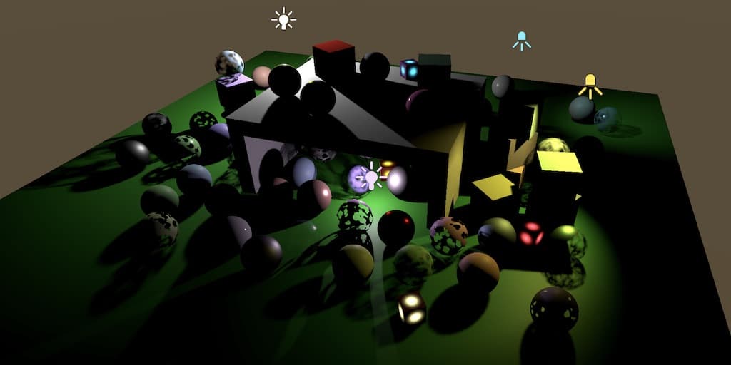
自定义渲染管线:点光源与聚光灯阴影 (翻译十)
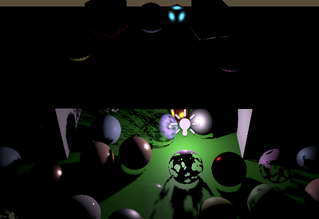
为点光源和聚光灯添加实时阴影支持,使用透视投影渲染和采样阴影,并使用自定义立方体贴图。
- 为点光源和聚光灯混合烘焙阴影和实时阴影。
- 添加第二个阴影图集。
- 使用透视投影渲染和采样阴影。
- 使用自定义立方体贴图。
这是关于创建自定义可编程渲染管线系列教程的第十部分。它为点光源和聚光灯添加了实时阴影支持。
本教程使用 Unity 2019.4.1f1 制作,并升级到 2022.3.5f1。
聚光灯阴影
我们首先为聚光灯添加实时阴影支持。我们将使用与方向光相同的方法,但会有一些变化。我们也会尽可能保持简单,使用均匀划分的阴影图集,并按照 Unity 提供的顺序填充有阴影的光源。
阴影混合
第一步是使烘焙阴影和实时阴影可以混合。修改 Shadows 中的 GetOtherShadowAttenuation,使其行为类似于 GetDirectionalShadowAttenuation,但它使用其他阴影数据并依赖于一个新的 GetOtherShadow 函数。新函数最初返回 1,因为其他光源还没有实时阴影。
1
2
3
4
5
6
7
8
9
10
11
12
13
14
15
16
17
18
19
20
21
22
23
24
25
26
27
float GetOtherShadow (
    OtherShadowData other, ShadowData global, Surface surfaceWS
) {
    return 1.0;
}

float GetOtherShadowAttenuation (
    OtherShadowData other, ShadowData global, Surface surfaceWS
) {
    #if !defined(_RECEIVE_SHADOWS)
        return 1.0;
    #endif

    float shadow;
    if (other.strength * global.strength <= 0.0) {
        shadow = GetBakedShadow(
            global.shadowMask, other.shadowMaskChannel, abs(other.strength)
        );
    }
    else {
        shadow = GetOtherShadow(other, global, surfaceWS);
        shadow = MixBakedAndRealtimeShadows(
            global, shadow, other.shadowMaskChannel, other.strength
        );
    }
    return shadow;
}
全局强度用于确定是否可以跳过实时阴影采样,原因可能是超出了阴影距离或位于最大级联球体之外。然而,级联仅适用于方向阴影。它们对其他光源没有意义,因为这些光源有固定位置,因此它们的阴影贴图不会随视图移动。话虽如此,以相同的方式淡出所有阴影是一个好主意,否则我们可能会在屏幕的某些区域没有方向阴影但有其他阴影。因此,我们对所有阴影使用相同的全局阴影强度。
我们必须处理的一个特殊情况是没有方向阴影但存在其他阴影的情况。当这种情况发生时,没有任何级联,因此它们不应影响全局阴影强度。我们仍然需要阴影距离淡入值。因此,让我们将设置级联计数和距离淡入的代码从 Shadows.RenderDirectionShadows 移到 Shadows.Render,并在适当的时候将级联计数设置为零。
1
2
3
4
5
6
7
8
9
10
11
12
13
14
15
16
17
18
19
20
21
22
23
24
25
26
27
28
29
30
31
32
33
34
public void Render () {
    ...
    buffer.SetGlobalInt(
        cascadeCountId,
        shadowedDirLightCount > 0 ? settings.directional.cascadeCount : 0
    );
    float f = 1f - settings.directional.cascadeFade;
    buffer.SetGlobalVector(
        shadowDistanceFadeId, new Vector4(
            1f / settings.maxDistance, 1f / settings.distanceFade,
            1f / (1f - f * f)
        )
    );
    buffer.EndSample(bufferName);
    ExecuteBuffer();
}

void RenderDirectionalShadows () {
    ...
    //buffer.SetGlobalInt(cascadeCountId, settings.directional.cascadeCount);
    buffer.SetGlobalVectorArray(
        cascadeCullingSpheresId, cascadeCullingSpheres
    );
    buffer.SetGlobalVectorArray(cascadeDataId, cascadeData);
    buffer.SetGlobalMatrixArray(dirShadowMatricesId, dirShadowMatrices);
    //float f = 1f - settings.directional.cascadeFade;
    //buffer.SetGlobalVector(
    //    shadowDistanceFadeId, new Vector4(
    //        1f / settings.maxDistance, 1f / settings.distanceFade,
    //        1f / (1f - f * f)
    //    )
    //);
    ...
}
然后我们必须确保在 GetShadowData 的级联循环之后,全局强度不会错误地设置为零。
1
2
3
if (i == _CascadeCount && _CascadeCount > 0) {
    data.strength = 0.0;
}
其他光源的实时阴影
方向阴影有自己的图集贴图。我们将为所有其他有阴影的光源使用单独的图集,并单独计数。让我们使用最多十六个其他光源支持实时阴影。
1
2
3
4
5
6
7
8
9
10
const int maxShadowedDirLightCount = 4, maxShadowedOtherLightCount = 16;
const int maxCascades = 4;
...
int shadowedDirLightCount, shadowedOtherLightCount;
...
public void Setup (...) {
    ...
    shadowedDirLightCount = shadowedOtherLightCount = 0;
    useShadowMask = false;
}
这意味着我们可能会遇到启用了阴影但无法放入图集的光源。哪些光源不会获得阴影取决于它们在可见光源列表中的位置。我们只是不为那些失去资格的光源预留阴影,但如果它们有烘焙阴影,我们仍然可以允许使用这些。为此,首先重构 ReserveOtherShadows,使其在光源没有阴影时立即返回。否则,它会检查阴影遮罩通道——默认使用 -1——然后始终返回阴影强度和通道。
1
2
3
4
5
6
7
8
9
10
11
12
13
14
15
16
17
18
19
20
21
22
23
public Vector4 ReserveOtherShadows (Light light, int visibleLightIndex) {
    if (light.shadows == LightShadows.None || light.shadowStrength <= 0f) {
        return new Vector4(0f, 0f, 0f, -1f);
    }

    float maskChannel = -1f;
    //if (light.shadows != LightShadows.None && light.shadowStrength > 0f) {
        LightBakingOutput lightBaking = light.bakingOutput;
        if (
            lightBaking.lightmapBakeType == LightmapBakeType.Mixed &&
            lightBaking.mixedLightingMode == MixedLightingMode.Shadowmask
        ) {
            useShadowMask = true;
            maskChannel = lightBaking.occlusionMaskChannel;
        }
        return new Vector4(
            light.shadowStrength, 0f, 0f,
            maskChannel
        );
    //}
    //}
    //return new Vector4(0f, 0f, 0f, -1f);
}
然后在返回之前检查增加光源计数是否会超过最大值,或者该光源是否没有阴影可渲染。如果是,则返回负的阴影强度和遮罩通道,以便在适当的时候使用烘焙阴影。否则继续增加光源计数并设置tiled索引。
1
2
3
4
5
6
7
8
9
10
11
if (
    shadowedOtherLightCount >= maxShadowedOtherLightCount ||
    !cullingResults.GetShadowCasterBounds(visibleLightIndex, out Bounds b)
) {
    return new Vector4(-light.shadowStrength, 0f, 0f, maskChannel);
}

return new Vector4(
    light.shadowStrength, shadowedOtherLightCount++, 0f,
    maskChannel
);
两个图集
因为方向阴影和其他阴影是分开的,我们可以对它们进行不同的配置。在 ShadowSettings 中为其他阴影添加一个新的配置结构和字段,只包含图集大小和过滤器,因为级联不适用。
1
2
3
4
5
6
7
8
9
10
[System.Serializable]
public struct Other {
    public MapSize atlasSize;
    public FilterMode filter;
}

public Other other = new Other {
    atlasSize = MapSize._1024,
    filter = FilterMode.PCF2x2
};

在我们的 Lit 着色器的 CustomLit pass 中添加一个 multi-compile 指令,以支持其他阴影的阴影过滤。
1
#pragma multi_compile _ _OTHER_PCF3 _OTHER_PCF5 _OTHER_PCF7
并在 Shadows 中添加相应的关键字数组。
1
2
3
4
5
static string[] otherFilterKeywords = {
    "_OTHER_PCF3",
    "_OTHER_PCF5",
    "_OTHER_PCF7",
};
我们还需要跟踪其他阴影图集和矩阵的着色器属性标识符,以及一个用于保存矩阵的数组。
1
2
3
4
5
6
7
8
9
10
static int
    dirShadowAtlasId = Shader.PropertyToID("_DirectionalShadowAtlas"),
    dirShadowMatricesId = Shader.PropertyToID("_DirectionalShadowMatrices"),
    otherShadowAtlasId = Shader.PropertyToID("_OtherShadowAtlas"),
    otherShadowMatricesId = Shader.PropertyToID("_OtherShadowMatrices"),
    ...;
...
static Matrix4x4[]
    dirShadowMatrices = new Matrix4x4[maxShadowedDirLightCount * maxCascades],
    otherShadowMatrices = new Matrix4x4[maxShadowedOtherLightCount];
我们已经使用向量的 XY 分量将方向图集的大小发送到 GPU。现在我们还需要发送其他图集的大小,可以将其放入同一向量的 ZW 分量中。将其提升为字段,并从 RenderDirectionalShadows 移动设置全局向量的操作到 Render。然后 RenderDirectionalShadows 只需要分配该字段的 XY 分量。
1
2
3
4
5
6
7
8
9
10
11
12
13
14
15
16
17
18
19
20
Vector4 atlasSizes;
...
public void Render () {
    ...
    buffer.SetGlobalVector(shadowAtlasSizeId, atlasSizes);
    buffer.EndSample(bufferName);
    ExecuteBuffer();
}

void RenderDirectionalShadows () {
    int atlasSize = (int)settings.directional.atlasSize;
    atlasSizes.x = atlasSize;
    atlasSizes.y = 1f / atlasSize;
    ...
    //buffer.SetGlobalVector(
    //    shadowAtlasSizeId, new Vector4(atlasSize, 1f / atlasSize)
    //);
    buffer.EndSample(bufferName);
    ExecuteBuffer();
}
之后,复制 RenderDirectionalShadows 并将其重命名为 RenderOtherShadows。修改它以使用正确的设置、图集、矩阵,并设置正确的大小分量。然后从中移除级联和剔除球体代码。同时移除对 RenderDirectionalShadows 的调用,但保留循环。
1
2
3
4
5
6
7
8
9
10
11
12
13
14
15
16
17
18
19
20
21
22
23
24
25
26
27
28
29
30
31
32
33
34
35
36
37
38
void RenderOtherShadows () {
    int atlasSize = (int)settings.other.atlasSize;
    atlasSizes.z = atlasSize;
    atlasSizes.w = 1f / atlasSize;

    buffer.GetTemporaryRT(
        otherShadowAtlasId, atlasSize, atlasSize,
        32, FilterMode.Bilinear, RenderTextureFormat.Shadowmap
    );
    buffer.SetRenderTarget(
        otherShadowAtlasId,
        RenderBufferLoadAction.DontCare, RenderBufferStoreAction.Store
    );
    buffer.ClearRenderTarget(true, false, Color.clear);
    buffer.BeginSample(bufferName);
    ExecuteBuffer();

    int tiles = shadowedOtherLightCount;
    int split = tiles <= 1 ? 1 : tiles <= 4 ? 2 : 4;
    int tileSize = atlasSize / split;

    for (int i = 0; i < shadowedOtherLightCount; i++) {
        //RenderDirectionalShadows(i, split, tileSize);
    }
    //buffer.SetGlobalVectorArray(
    //    cascadeCullingSpheresId, cascadeCullingSpheres
    //);
    //buffer.SetGlobalVectorArray(cascadeDataId, cascadeData);
    buffer.SetGlobalMatrixArray(otherShadowMatricesId, otherShadowMatrices);
    SetKeywords(
        otherFilterKeywords, (int)settings.other.filter - 1
    );
    //SetKeywords(
    //    cascadeBlendKeywords, (int)settings.directional.cascadeBlend - 1
    //);
    buffer.EndSample(bufferName);
    ExecuteBuffer();
}
现在我们可以在 RenderShadows 中根据需要渲染方向阴影和其他阴影。如果没有其他阴影,我们需要为它们提供一个虚拟纹理,就像方向阴影一样。我们可以简单地使用方向阴影图集作为虚拟纹理。
1
2
3
4
5
6
7
8
9
10
11
12
13
14
15
16
17
18
19
public void Render () {
    if (shadowedDirLightCount > 0) {
        RenderDirectionalShadows();
    }
    else {
        buffer.GetTemporaryRT(
            dirShadowAtlasId, 1, 1,
            32, FilterMode.Bilinear, RenderTextureFormat.Shadowmap
        );
    }

    if (shadowedOtherLightCount > 0) {
        RenderOtherShadows();
    }
    else {
        buffer.SetGlobalTexture(otherShadowAtlasId, dirShadowAtlasId);
    }
    ...
}
并在 Cleanup 中释放其他阴影图集,在这种情况下仅当我们确实获得了一个。
1
2
3
4
5
6
7
public void Cleanup () {
    buffer.ReleaseTemporaryRT(dirShadowAtlasId);
    if (shadowedOtherLightCount > 0) {
        buffer.ReleaseTemporaryRT(otherShadowAtlasId);
    }
    ExecuteBuffer();
}
渲染聚光灯阴影
要渲染聚光灯的阴影,我们需要知道它的可见光源索引、斜率缩放偏移和法线偏移。因此创建一个 ShadowedOtherLight 结构,其中包含这些字段,并为其添加一个数组字段,类似于我们跟踪方向阴影数据的方式。
1
2
3
4
5
6
7
8
struct ShadowedOtherLight {
    public int visibleLightIndex;
    public float slopeScaleBias;
    public float normalBias;
}

ShadowedOtherLight[] shadowedOtherLights =
    new ShadowedOtherLight[maxShadowedOtherLightCount];
在 ReserveOtherShadows 结束时、返回之前复制相关数据。
1
2
3
4
5
6
7
8
9
10
11
12
public Vector4 ReserveOtherShadows (Light light, int visibleLightIndex) {
    ...
    shadowedOtherLights[shadowedOtherLightCount] = new ShadowedOtherLight {
        visibleLightIndex = visibleLightIndex,
        slopeScaleBias = light.shadowBias,
        normalBias = light.shadowNormalBias
    };
    return new Vector4(
        light.shadowStrength, shadowedOtherLightCount++, 0f,
        maskChannel
    );
}
然而,此时我们应该意识到,我们无法保证在 Lighting 中向 ReserveOtherShadows 发送正确的光源索引,因为它传递的是自己用于其他光源的索引。当存在有阴影的方向光源时,该索引将是错误的。我们通过为光源设置方法添加一个参数来传递正确的可见光源索引来修复这个问题,并在预留阴影时使用该索引。为了一致性,我们也对方向光源这样做。
1
2
3
4
5
6
7
8
9
10
11
12
13
14
15
16
17
18
19
20
21
22
23
void SetupDirectionalLight (
    int index, int visibleIndex, ref VisibleLight visibleLight
) {
    ...
    dirLightShadowData[index] =
        shadows.ReserveDirectionalShadows(visibleLight.light, visibleIndex);
}

void SetupPointLight (
    int index, int visibleIndex, ref VisibleLight visibleLight
) {
    ...
    otherLightShadowData[index] =
        shadows.ReserveOtherShadows(light, visibleIndex);
}

void SetupSpotLight (
    int index, int visibleIndex, ref VisibleLight visibleLight
) {
    ...
    otherLightShadowData[index] =
        shadows.ReserveOtherShadows(light, visibleIndex);
}
调整 SetupLights 以将可见光源索引传递给设置方法。
1
2
3
4
5
6
7
8
9
10
11
12
13
14
15
16
17
18
19
20
21
switch (visibleLight.lightType) {
    case LightType.Directional:
        if (dirLightCount < maxDirLightCount) {
            SetupDirectionalLight(
                dirLightCount++, i, ref visibleLight
            );
        }
        break;
    case LightType.Point:
        if (otherLightCount < maxOtherLightCount) {
            newIndex = otherLightCount;
            SetupPointLight(otherLightCount++, i, ref visibleLight);
        }
        break;
    case LightType.Spot:
        if (otherLightCount < maxOtherLightCount) {
            newIndex = otherLightCount;
            SetupSpotLight(otherLightCount++, i, ref visibleLight);
        }
        break;
}
回到 Shadows,创建一个 RenderSpotShadows 方法,其功能与带参数的 RenderDirectionalShadows 方法相同,不同之处在于它不循环多个tiled、没有级联、也没有剔除因子。在这种情况下,我们可以使用 CullingResults.ComputeSpotShadowMatricesAndCullingPrimitives,它的工作方式类似于 ComputeDirectionalShadowMatricesAndCullingPrimitives,不同之处在于它只有可见光源索引、矩阵和分割数据作为参数。在 Unity 2022 中,我们还必须使用 BatchCullingProjectionType.Perspective 而不是正交投影。
1
2
3
4
5
6
7
8
9
10
11
12
13
14
15
16
17
18
19
20
21
void RenderSpotShadows (int index, int split, int tileSize) {
    ShadowedOtherLight light = shadowedOtherLights[index];
    var shadowSettings = new ShadowDrawingSettings(
        cullingResults, light.visibleLightIndex,
        BatchCullingProjectionType.Perspective
    );
    cullingResults.ComputeSpotShadowMatricesAndCullingPrimitives(
        light.visibleLightIndex, out Matrix4x4 viewMatrix,
        out Matrix4x4 projectionMatrix, out ShadowSplitData splitData
    );
    shadowSettings.splitData = splitData;
    otherShadowMatrices[index] = ConvertToAtlasMatrix(
        projectionMatrix * viewMatrix,
        SetTileViewport(index, split, tileSize), split
    );
    buffer.SetViewProjectionMatrices(viewMatrix, projectionMatrix);
    buffer.SetGlobalDepthBias(0f, light.slopeScaleBias);
    ExecuteBuffer();
    context.DrawShadows(ref shadowSettings);
    buffer.SetGlobalDepthBias(0f, 0f);
}
在 RenderOtherShadows 的循环内调用此方法。
1
2
3
for (int i = 0; i < shadowedOtherLightCount; i++) {
    RenderSpotShadows(i, split, tileSize);
}
禁用 Pancaking
阴影现在可以为聚光灯渲染,使用与方向阴影相同的 ShadowCaster pass。这工作正常,但阴影 pancaking 只对正交阴影投影有效,用于被认为是无限远方向光源。对于聚光灯——它们确实有位置——阴影投射者可能最终部分位于光源位置后面。由于在这种情况下我们使用透视投影,将顶点约束到近平面会严重扭曲这些阴影。因此,当 pancaking 不适用时,我们应该关闭约束。
我们可以通过全局着色器属性告诉着色器 pancaking 是否激活,我们将其命名为 _ShadowPancaking。在 Shadows 中跟踪其标识符。
1
2
3
4
static int
    ...
    shadowDistanceFadeId = Shader.PropertyToID("_ShadowDistanceFade"),
    shadowPancakingId = Shader.PropertyToID("_ShadowPancaking");
在 RenderDirectionalShadows 渲染阴影之前将其设置为 1。
1
2
3
buffer.ClearRenderTarget(true, false, Color.clear);
buffer.SetGlobalFloat(shadowPancakingId, 1f);
buffer.BeginSample(bufferName);
并在 RenderOtherShadows 中将其设置为零。
1
2
3
buffer.ClearRenderTarget(true, false, Color.clear);
buffer.SetGlobalFloat(shadowPancakingId, 0f);
buffer.BeginSample(bufferName);
然后将其作为布尔值添加到我们的 Lit 着色器的 ShadowCaster pass 中,仅在适当的时候使用它来约束。
1
2
3
4
5
6
7
8
9
10
11
12
13
14
15
16
17
18
bool _ShadowPancaking;

Varyings ShadowCasterPassVertex (Attributes input) {
    ...
    if (_ShadowPancaking) {
        #if UNITY_REVERSED_Z
            output.positionCS.z = min(
                output.positionCS.z, output.positionCS.w * UNITY_NEAR_CLIP_VALUE
            );
        #else
            output.positionCS.z = max(
                output.positionCS.z, output.positionCS.w * UNITY_NEAR_CLIP_VALUE
            );
        #endif
    }
    output.baseUV = TransformBaseUV(input.baseUV);
    return output;
}
采样聚光灯阴影
要采样其他阴影,我们必须调整 Shadows。首先定义其他过滤器和最大有阴影其他光源计数宏。然后添加其他阴影图集和其他阴影矩阵数组。
1
2
3
4
5
6
7
8
9
10
11
12
13
14
15
16
17
18
19
20
21
22
23
24
25
26
27
#if defined(_OTHER_PCF3)
    #define OTHER_FILTER_SAMPLES 4
    #define OTHER_FILTER_SETUP SampleShadow_ComputeSamples_Tent_3x3
#elif defined(_OTHER_PCF5)
    #define OTHER_FILTER_SAMPLES 9
    #define OTHER_FILTER_SETUP SampleShadow_ComputeSamples_Tent_5x5
#elif defined(_OTHER_PCF7)
    #define OTHER_FILTER_SAMPLES 16
    #define OTHER_FILTER_SETUP SampleShadow_ComputeSamples_Tent_7x7
#endif

#define MAX_SHADOWED_DIRECTIONAL_LIGHT_COUNT 4
#define MAX_SHADOWED_OTHER_LIGHT_COUNT 16
#define MAX_CASCADE_COUNT 4

TEXTURE2D_SHADOW(_DirectionalShadowAtlas);
TEXTURE2D_SHADOW(_OtherShadowAtlas);
#define SHADOW_SAMPLER sampler_linear_clamp_compare
SAMPLER_CMP(SHADOW_SAMPLER);

CBUFFER_START(_CustomShadows)
    ...
    float4x4 _DirectionalShadowMatrices
        [MAX_SHADOWED_DIRECTIONAL_LIGHT_COUNT * MAX_CASCADE_COUNT];
    float4x4 _OtherShadowMatrices[MAX_SHADOWED_OTHER_LIGHT_COUNT];
    ...
CBUFFER_END
复制 SampleDirectionalShadowAtlas 和 FilterDirectionalShadow,并将它们重命名并调整以适用于其他阴影。请注意,对于此版本,我们需要使用图集大小向量的另一个分量对。
1
2
3
4
5
6
7
8
9
10
11
12
13
14
15
16
17
18
19
20
21
22
23
float SampleOtherShadowAtlas (float3 positionSTS) {
    return SAMPLE_TEXTURE2D_SHADOW(
        _OtherShadowAtlas, SHADOW_SAMPLER, positionSTS
    );
}

float FilterOtherShadow (float3 positionSTS) {
    #if defined(OTHER_FILTER_SETUP)
        real weights[OTHER_FILTER_SAMPLES];
        real2 positions[OTHER_FILTER_SAMPLES];
        float4 size = _ShadowAtlasSize.wwzz;
        OTHER_FILTER_SETUP(size, positionSTS.xy, weights, positions);
        float shadow = 0;
        for (int i = 0; i < OTHER_FILTER_SAMPLES; i++) {
            shadow += weights[i] * SampleOtherShadowAtlas(
                float3(positions[i].xy, positionSTS.z)
            );
        }
        return shadow;
    #else
        return SampleOtherShadowAtlas(positionSTS);
    #endif
}
OtherShadowData 结构现在也需要一个tiled索引。
1
2
3
4
5
struct OtherShadowData {
    float strength;
    int tileIndex;
    int shadowMaskChannel;
};
它由 Light 中的 GetOtherShadowData 设置。
1
2
3
4
5
6
7
OtherShadowData GetOtherShadowData (int lightIndex) {
    OtherShadowData data;
    data.strength = _OtherLightShadowData[lightIndex].x;
    data.tileIndex = _OtherLightShadowData[lightIndex].y;
    data.shadowMaskChannel = _OtherLightShadowData[lightIndex].w;
    return data;
}
现在我们可以在 GetOtherShadow 中采样阴影贴图,而不是总是返回 1。它的工作方式类似于 GetCascadedShadow,不同之处在于没有第二个级联需要混合,并且它是透视投影,因此我们必须将转换后位置的 XYZ 分量除以其 W 分量。此外,我们还没有功能性的法线偏移,所以我们现在将其乘以零。
1
2
3
4
5
6
7
8
9
10
float GetOtherShadow (
    OtherShadowData other, ShadowData global, Surface surfaceWS
) {
    float3 normalBias = surfaceWS.interpolatedNormal * 0.0;
    float4 positionSTS = mul(
        _OtherShadowMatrices[other.tileIndex],
        float4(surfaceWS.position + normalBias, 1.0)
    );
    return FilterOtherShadow(positionSTS.xyz / positionSTS.w);
}

法线偏移
聚光灯与方向光一样会遭受阴影痤疮(shadow acne)。但由于透视投影,纹素大小不是恒定的,因此痤疮也不恒定。距离光源越远,痤疮越大。
纹素大小随距光平面的距离线性增加,光平面是将世界分成光前和光后的平面。因此,我们可以在距离 1 处计算纹素大小,从而计算法线偏移,并将其发送到着色器,在那里我们将其缩放到适当的大小。
在世界空间中,距离光平面距离为 1 时,阴影tiled的大小是聚光角度一半弧度的正切值的两倍。
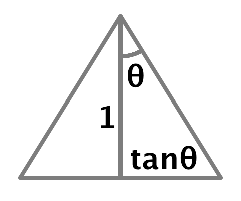
这与透视投影相匹配,因此距离 1 处的世界空间纹素大小等于 2 除以投影缩放,我们可以使用其矩阵的左上角值。我们可以使用它来计算法线偏移,方法与方向光相同,不同之处在于我们可以立即将光源的法线偏移纳入其中,因为没有多个级联。在 Shadows.RenderSpotShadows 中设置阴影矩阵之前执行此操作。
1
2
3
4
5
6
7
float texelSize = 2f / (tileSize * projectionMatrix.m00);
float filterSize = texelSize * ((float)settings.other.filter + 1f);
float bias = light.normalBias * filterSize * 1.4142136f;
otherShadowMatrices[index] = ConvertToAtlasMatrix(
    projectionMatrix * viewMatrix,
    SetTileViewport(index, split, tileSize), tileScale
);
现在我们必须将偏移发送到着色器。稍后我们需要为每个tiled发送更多数据,因此让我们添加一个 _OtherShadowTiles 向量数组着色器属性。为其添加标识符和数组到 Shadows,并在 RenderOtherShadows 中与矩阵一起设置它。
1
2
3
4
5
6
7
8
9
10
11
12
13
14
15
16
17
static int
    ...
    otherShadowMatricesId = Shader.PropertyToID("_OtherShadowMatrices"),
    otherShadowTilesId = Shader.PropertyToID("_OtherShadowTiles"),
    ...;

static Vector4[]
    cascadeCullingSpheres = new Vector4[maxCascades],
    cascadeData = new Vector4[maxCascades],
    otherShadowTiles = new Vector4[maxShadowedOtherLightCount];
...
void RenderOtherShadows () {
    ...
    buffer.SetGlobalMatrixArray(otherShadowMatricesId, otherShadowMatrices);
    buffer.SetGlobalVectorArray(otherShadowTilesId, otherShadowTiles);
    ...
}
创建一个新的 SetOtherTileData 方法,带有索引和偏移参数。让它将偏移放在向量的最后一个分量中,然后将其存储在tiled数据数组中。
1
2
3
4
5
void SetOtherTileData (int index, float bias) {
    Vector4 data = Vector4.zero;
    data.w = bias;
    otherShadowTiles[index] = data;
}
在 RenderSpotShadows 中一旦我们有了偏移就调用它。
1
2
float bias = light.normalBias * filterSize * 1.4142136f;
SetOtherTileData(index, bias);
然后将其他阴影tiled数组添加到阴影缓冲区,并使用它在 Shadows 中缩放法线偏移。
1
2
3
4
5
6
7
8
9
10
11
12
13
14
15
CBUFFER_START(_CustomShadows)
    ...
    float4x4 _OtherShadowMatrices[MAX_SHADOWED_OTHER_LIGHT_COUNT];
    float4 _OtherShadowTiles[MAX_SHADOWED_OTHER_LIGHT_COUNT];
    float4 _ShadowAtlasSize;
    float4 _ShadowDistanceFade;
CBUFFER_END
...
float GetOtherShadow (
    OtherShadowData other, ShadowData global, Surface surfaceWS
) {
    float4 tileData = _OtherShadowTiles[other.tileIndex];
    float3 normalBias = surfaceWS.interpolatedNormal * tileData.w;
    ...
}
此时我们的法线偏移仅在固定距离处是正确的。要使其随距光平面的距离缩放,我们需要知道世界空间光源位置和聚光方向,因此将它们添加到 OtherShadowData。
1
2
3
4
5
6
7
struct OtherShadowData {
    float strength;
    int tileIndex;
    int shadowMaskChannel;
    float3 lightPositionWS;
    float3 spotDirectionWS;
};
让 Light 将值复制到其中。由于这些值来自光源本身而不是阴影数据,因此在 GetOtherShadowData 中将它们设置为零,并在 GetOtherLight 中复制它们。
1
2
3
4
5
6
7
8
9
10
11
12
13
14
15
16
17
18
19
20
21
22
23
OtherShadowData GetOtherShadowData (int lightIndex) {
    ...
    data.lightPositionWS = 0.0;
    data.spotDirectionWS = 0.0;
    return data;
}

Light GetOtherLight (int index, Surface surfaceWS, ShadowData shadowData) {
    Light light;
    light.color = _OtherLightColors[index].rgb;
    float3 position = _OtherLightPositions[index].xyz;
    float3 ray = position - surfaceWS.position;
    ...
    float3 spotDirection = _OtherLightDirections[index].xyz;
    float spotAttenuation = Square(
        saturate(dot(spotDirection, light.direction) *
        spotAngles.x + spotAngles.y)
    );
    OtherShadowData otherShadowData = GetOtherShadowData(index);
    otherShadowData.lightPositionWS = position;
    otherShadowData.spotDirectionWS = spotDirection;
    ...
}
我们通过在 GetOtherShadow 中取表面到光源向量与聚光方向的点积来找到到平面的距离。使用它来缩放法线偏移。
1
2
3
4
5
float4 tileData = _OtherShadowTiles[other.tileIndex];
float3 surfaceToLight = other.lightPositionWS - surfaceWS.position;
float distanceToLightPlane = dot(surfaceToLight, other.spotDirectionWS);
float3 normalBias =
    surfaceWS.interpolatedNormal * (distanceToLightPlane * tileData.w);
约束采样
我们为方向阴影配置了级联球体,以确保永远不会在适当的阴影tiled之外采样,但我们不能对其他阴影使用相同的方法。对于聚光灯,它们的tiled紧密贴合其圆锥体,因此法线偏移和过滤器大小将在圆锥边缘接近tiled边缘的地方将采样推到tiled边界之外。
解决这个问题的最简单方法是手动约束采样以保持在tiled边界内,就好像每个tiled都是自己的单独纹理一样。这仍然会在边缘附近拉伸阴影,但不会引入无效阴影。
调整 SetOtherTileData 方法,使其还根据通过新参数提供的偏移和缩放来计算和存储tiled边界。tiled的最小纹理坐标是缩放的偏移,我们将其存储在数据向量的 XY 分量中。由于tiled是正方形的,我们可以只在 Z 分量中存储tiled的缩放,将 W 留给偏移。我们还必须在两个维度上将边界缩小半个纹素,以确保采样不会超出边缘。
1
2
3
4
5
6
7
8
9
void SetOtherTileData (int index, Vector2 offset, float scale, float bias) {
    float border = atlasSizes.w * 0.5f;
    Vector4 data;
    data.x = offset.x * scale + border;
    data.y = offset.y * scale + border;
    data.z = scale - border - border;
    data.w = bias;
    otherShadowTiles[index] = data;
}
在 RenderSpotShadows 中,使用通过 SetTileViewport 找到的偏移和分割的倒数作为 SetOtherTileData 的新参数。
1
2
3
4
5
Vector2 offset = SetTileViewport(index, split, tileSize);
SetOtherTileData(index, offset, 1f / split, bias);
otherShadowMatrices[index] = ConvertToAtlasMatrix(
    projectionMatrix * viewMatrix, offset, split
);
ConverToAtlasMatrix 方法也使用分割的倒数,因此我们可以计算一次并将其传递给两个方法。
1
2
3
4
5
float tileScale = 1f / split;
SetOtherTileData(index, offset, tileScale, bias);
otherShadowMatrices[index] = ConvertToAtlasMatrix(
    projectionMatrix * viewMatrix, offset, tileScale
);
然后 ConvertToAtlasMatrix 就不必自己执行除法了。
1
2
3
4
5
Matrix4x4 ConvertToAtlasMatrix (Matrix4x4 m, Vector2 offset, float scale) {
    ...
    //float scale = 1f / split;
    ...
}
这需要 RenderDirectionalShadows 执行除法,它只需要为所有级联执行一次。
1
2
3
4
5
6
7
8
9
10
11
12
void RenderDirectionalShadows (int index, int split, int tileSize) {
    ...
    float tileScale = 1f / split;
    for (int i = 0; i < cascadeCount; i++) {
        ...
        dirShadowMatrices[tileIndex] = ConvertToAtlasMatrix(
            projectionMatrix * viewMatrix,
            SetTileViewport(tileIndex, split, tileSize), tileScale
        );
        ...
    }
}
要应用边界,请为 SampleOtherShadowAtlas 添加一个 float3 参数,并使用它来约束阴影tiled空间中的位置。FilterOtherShadows 需要相同的参数,以便它可以传递它。而 GetOtherShadow 从tiled数据中检索它。
1
2
3
4
5
6
7
8
9
10
11
12
13
14
15
16
17
18
19
20
21
22
23
24
25
26
27
float SampleOtherShadowAtlas (float3 positionSTS, float3 bounds) {
    positionSTS.xy = clamp(positionSTS.xy, bounds.xy, bounds.xy + bounds.z);
    return SAMPLE_TEXTURE2D_SHADOW(
        _OtherShadowAtlas, SHADOW_SAMPLER, positionSTS
    );
}

float FilterOtherShadow (float3 positionSTS, float3 bounds) {
    #if defined(OTHER_FILTER_SETUP)
        ...
        for (int i = 0; i < OTHER_FILTER_SAMPLES; i++) {
            shadow += weights[i] * SampleOtherShadowAtlas(
                float3(positions[i].xy, positionSTS.z), bounds
            );
        }
        return shadow;
    #else
        return SampleOtherShadowAtlas(positionSTS, bounds);
    #endif
}

float GetOtherShadow (
    OtherShadowData other, ShadowData global, Surface surfaceWS
) {
    ...
    return FilterOtherShadow(positionSTS.xyz / positionSTS.w, tileData.xyz);
}
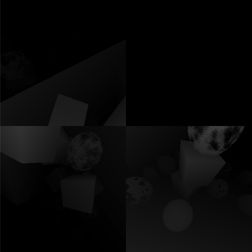
点光源阴影
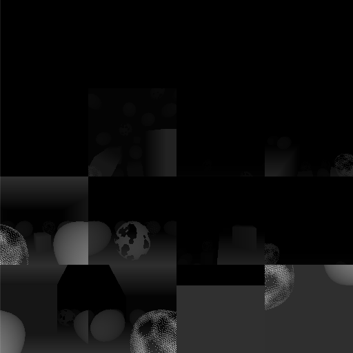
点光源的阴影工作方式类似于聚光灯。不同之处在于点光源不限于圆锥体,因此我们需要将它们的阴影渲染到立方体贴图。这是通过分别渲染立方体所有六个面的阴影来完成的。因此,为了实时阴影的目的,我们将点光源视为六个光源。它将占用阴影图集中的六个tiled。这意味着我们最多可以同时支持两个点光源的实时阴影,因为它们将占用十六个可用tiled中的十二个。如果可用tiled少于六个,点光源将无法获得实时阴影。
一个光源的六个tiled
首先,我们需要在渲染阴影时知道我们正在处理点光源,因此向 ShadowedOtherLight 添加一个布尔值来指示这一点。
1
2
3
4
struct ShadowedOtherLight {
    ...
    public bool isPoint;
}
在 ReserveOtherShadows 中检查我们是否有点光源。如果是,包括此光源在内的新光源计数将比当前计数大六,否则只大一。如果这会超过最大值,那么光源最多只能有烘焙阴影。如果图集中有足够的空间,则还要在返回的阴影数据的第三个分量中存储它是否为点光源,以便在着色器中轻松检测点光源。
1
2
3
4
5
6
7
8
9
10
11
12
13
14
15
16
17
18
19
20
21
22
23
24
public Vector4 ReserveOtherShadows (Light light, int visibleLightIndex) {
    ...
    bool isPoint = light.type == LightType.Point;
    int newLightCount = shadowedOtherLightCount + (isPoint ? 6 : 1);
    if (
        newLightCount > maxShadowedOtherLightCount ||
        !cullingResults.GetShadowCasterBounds(visibleLightIndex, out Bounds b)
    ) {
        return new Vector4(-light.shadowStrength, 0f, 0f, maskChannel);
    }

    shadowedOtherLights[shadowedOtherLightCount] = new ShadowedOtherLight {
        visibleLightIndex = visibleLightIndex,
        slopeScaleBias = light.shadowBias,
        normalBias = light.shadowNormalBias,
        isPoint = isPoint
    };
    Vector4 data = new Vector4(
        light.shadowStrength, shadowedOtherLightCount,
        isPoint ? 1f : 0f, maskChannel
    );
    shadowedOtherLightCount = newLightCount;
    return data;
}
渲染点光源阴影
调整 RenderOtherShadows,使其在循环中根据需要调用新的 RenderPointShadows 方法或现有的 RenderSpotShadows 方法。此外,由于点光源计为六个,因此为每种光源类型增加迭代器的正确数量,而不是仅递增它。
1
2
3
4
5
6
7
8
9
10
for (int i = 0; i < shadowedOtherLightCount;) { //i++) {
    if (shadowedOtherLights[i].isPoint) {
        RenderPointShadows(i, split, tileSize);
        i += 6;
    }
    else {
        RenderSpotShadows(i, split, tileSize);
        i += 1;
    }
}
新的 RenderPointShadows 方法是 RenderSpotShadows 的副本,有两个不同之处。首先,它必须渲染六次而不是只渲染一次,循环遍历其六个tiled。其次,它必须使用 ComputePointShadowMatricesAndCullingPrimitives 而不是 ComputeSpotShadowMatricesAndCullingPrimitives。此方法在光源索引之后需要两个额外的参数:一个 CubemapFace 索引和一个偏移。我们为每个面渲染一次,现在将偏移保留为零。
1
2
3
4
5
6
7
8
9
10
11
12
13
14
15
16
17
18
19
20
21
22
23
24
25
26
27
28
29
30
31
void RenderPointShadows (int index, int split, int tileSize) {
    ShadowedOtherLight light = shadowedOtherLights[index];
    var shadowSettings = new ShadowDrawingSettings(
        cullingResults, light.visibleLightIndex,
        BatchCullingProjectionType.Perspective
    );
    for (int i = 0; i < 6; i++) {
        cullingResults.ComputePointShadowMatricesAndCullingPrimitives(
            light.visibleLightIndex, (CubemapFace)i, 0f,
            out Matrix4x4 viewMatrix, out Matrix4x4 projectionMatrix,
            out ShadowSplitData splitData
        );
        shadowSettings.splitData = splitData;
        int tileIndex = index + i;
        float texelSize = 2f / (tileSize * projectionMatrix.m00);
        float filterSize = texelSize * ((float)settings.other.filter + 1f);
        float bias = light.normalBias * filterSize * 1.4142136f;
        Vector2 offset = SetTileViewport(tileIndex, split, tileSize);
        float tileScale = 1f / split;
        SetOtherTileData(tileIndex, offset, tileScale, bias);
        otherShadowMatrices[tileIndex] = ConvertToAtlasMatrix(
            projectionMatrix * viewMatrix, offset, tileScale
        );

        buffer.SetViewProjectionMatrices(viewMatrix, projectionMatrix);
        buffer.SetGlobalDepthBias(0f, light.slopeScaleBias);
        ExecuteBuffer();
        context.DrawShadows(ref shadowSettings);
        buffer.SetGlobalDepthBias(0f, 0f);
    }
}
立方体贴图面的视野始终为 90°,因此距离 1 处的世界空间tiled大小始终为 2。这意味着我们可以将偏移的计算提升到循环之外。我们也可以对tiled缩放这样做。
1
2
3
4
5
6
7
8
9
10
11
12
13
float texelSize = 2f / tileSize;
float filterSize = texelSize * ((float)settings.other.filter + 1f);
float bias = light.normalBias * filterSize * 1.4142136f;
float tileScale = 1f / split;
for (int i = 0; i < 6; i++) {
    ...
    //float texelSize = 2f / (tileSize * projectionMatrix.m00);
    //float filterSize = texelSize * ((float)settings.other.filter + 1f);
    //float bias = light.normalBias * filterSize * 1.4142136f;
    Vector2 offset = SetTileViewport(tileIndex, split, tileSize);
    //float tileScale = 1f / split;
    ...
}
采样点光源阴影
其思想是点光源阴影存储在立方体贴图中,着色器对其进行采样。然而,我们将立方体贴图面作为tiled存储在图集中,因此我们不能使用标准立方体贴图采样。我们必须自己确定要从中采样的适当面。为此,我们需要知道我们是否正在处理点光源以及表面到光源的方向。将两者都添加到 OtherShadowData。
1
2
3
4
5
6
7
8
9
struct OtherShadowData {
    float strength;
    int tileIndex;
    bool isPoint;
    int shadowMaskChannel;
    float3 lightPositionWS;
    float3 lightDirectionWS;
    float3 spotDirectionWS;
};
在 Light 中设置两个值。如果其他光源的阴影数据的第三个分量等于 1,则它是点光源。
1
2
3
4
5
6
7
8
9
10
11
12
13
14
15
16
OtherShadowData GetOtherShadowData (int lightIndex) {
    ...
    data.isPoint = _OtherLightShadowData[lightIndex].z == 1.0;
    data.lightPositionWS = 0.0;
    data.lightDirectionWS = 0.0;
    data.spotDirectionWS = 0.0;
    return data;
}

Light GetOtherLight (int index, Surface surfaceWS, ShadowData shadowData) {
    ...
    otherShadowData.lightPositionWS = position;
    otherShadowData.lightDirectionWS = light.direction;
    otherShadowData.spotDirectionWS = spotDirection;
    ...
}
接下来,在点光源的情况下,我们必须调整 GetOtherShadow 中的tiled索引和光平面。首先将它们转换为变量,最初为聚光灯配置。将tiled索引设为浮点数,因为我们将向其添加一个也定义为浮点数的偏移。
1
2
3
4
5
6
7
8
9
10
11
12
13
14
15
16
float GetOtherShadow (
    OtherShadowData other, ShadowData global, Surface surfaceWS
) {
    float tileIndex = other.tileIndex;
    float3 lightPlane = other.spotDirectionWS;
    float4 tileData = _OtherShadowTiles[tileIndex];
    float3 surfaceToLight = other.lightPositionWS - surfaceWS.position;
    float distanceToLightPlane = dot(surfaceToLight, lightPlane);
    float3 normalBias =
        surfaceWS.interpolatedNormal * (distanceToLightPlane * tileData.w);
    float4 positionSTS = mul(
        _OtherShadowMatrices[tileIndex],
        float4(surfaceWS.position + normalBias, 1.0)
    );
    return FilterOtherShadow(positionSTS.xyz / positionSTS.w, tileData.xyz);
}
如果我们有点光源,那么我们必须使用适当的轴对齐平面。我们可以使用 CubeMapFaceID 函数通过传递取反的光方向来找到面偏移。此函数要么是内在的,要么在 Core RP Library 中定义,返回一个浮点数。立方体贴图面的顺序是 +X、−X、+Y、−Y、+Z、−Z,这与我们渲染它们的方式相匹配。将偏移添加到tiled索引。
1
2
3
4
5
6
7
8
9
10
11
float GetOtherShadow (
    OtherShadowData other, ShadowData global, Surface surfaceWS
) {
    float tileIndex = other.tileIndex;
    float3 lightPlane = other.spotDirectionWS;
    if (other.isPoint) {
        float faceOffset = CubeMapFaceID(-other.lightDirectionWS);
        tileIndex += faceOffset;
    }
    ...
}
接下来,我们需要使用与面方向匹配的光平面。为它们创建一个静态常量数组,并使用面偏移来索引它。平面法线必须指向与面相反的方向,就像聚光方向指向光源一样。
1
2
3
4
5
6
7
8
9
10
11
12
13
14
15
16
17
18
19
20
21
static const float3 pointShadowPlanes[6] = {
    float3(-1.0, 0.0, 0.0),
    float3(1.0, 0.0, 0.0),
    float3(0.0, -1.0, 0.0),
    float3(0.0, 1.0, 0.0),
    float3(0.0, 0.0, -1.0),
    float3(0.0, 0.0, 1.0)
};

float GetOtherShadow (
    OtherShadowData other, ShadowData global, Surface surfaceWS
) {
    float tileIndex = other.tileIndex;
    float3 plane = other.spotDirectionWS;
    if (other.isPoint) {
        float faceOffset = CubeMapFaceID(-other.lightDirectionWS);
        tileIndex += faceOffset;
        lightPlane = pointShadowPlanes[faceOffset];
    }
    ...
}
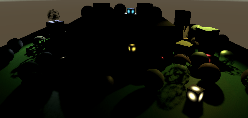
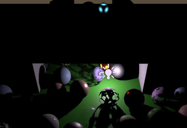
绘制正确的面
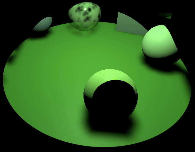
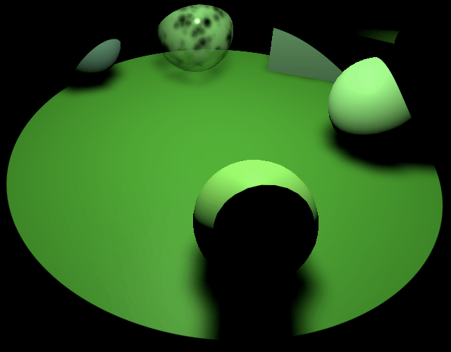
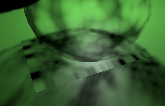
我们现在可以看到点光源的实时阴影。即使偏移为零,它们似乎也不会受到阴影痤疮的影响。不幸的是,光现在会通过物体泄漏到相反一侧非常接近它们的表面。增加阴影偏移会使这种情况变得更糟,并且似乎还会在靠近其他表面的物体阴影中切出孔洞。
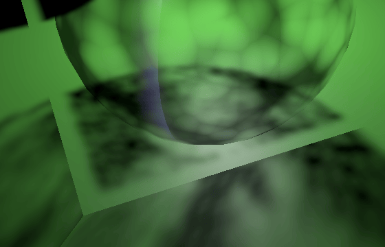
这是因为 Unity 渲染点光源阴影的方式。它将它们倒置绘制,这会反转三角形的缠绕顺序。通常会绘制前面(从光源的角度来看),但现在会渲染背面。这可以防止大多数痤疮,但会引入光泄漏。我们无法阻止翻转,但我们可以通过取反从 ComputePointShadowMatricesAndCullingPrimitives 获得的视图矩阵的一行来撤消它。让我们取反其第二行。这会第二次在图集中将所有内容上下翻转,这会将所有内容恢复正常。因为该行的第一个分量始终为零,我们只需取反其他三个分量即可。
1
2
3
4
5
6
7
8
cullingResults.ComputePointShadowMatricesAndCullingPrimitives(
    light.visibleLightIndex, (CubemapFace)i, fovBias,
    out Matrix4x4 viewMatrix, out Matrix4x4 projectionMatrix,
    out ShadowSplitData splitData
);
viewMatrix.m11 = -viewMatrix.m11;
viewMatrix.m12 = -viewMatrix.m12;
viewMatrix.m13 = -viewMatrix.m13;

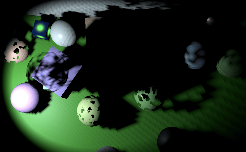
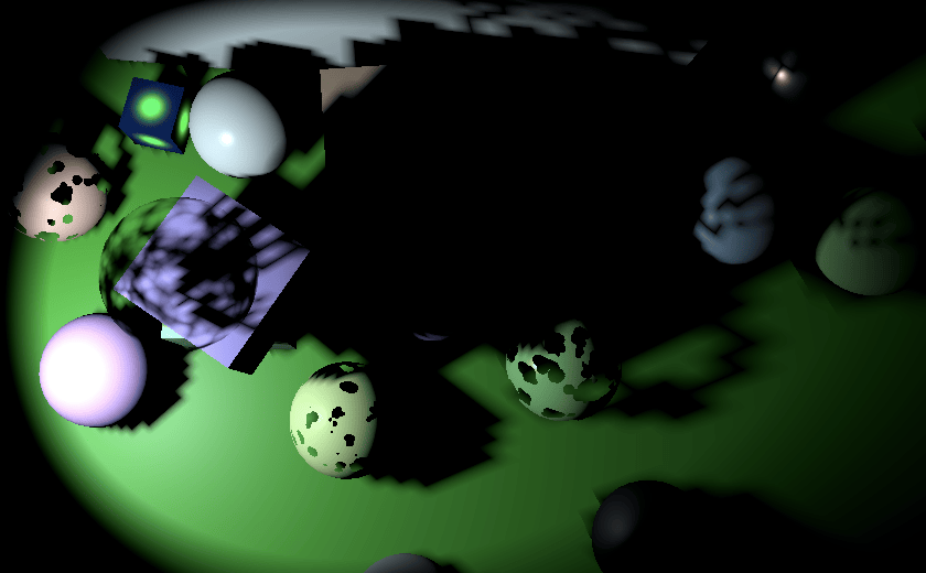
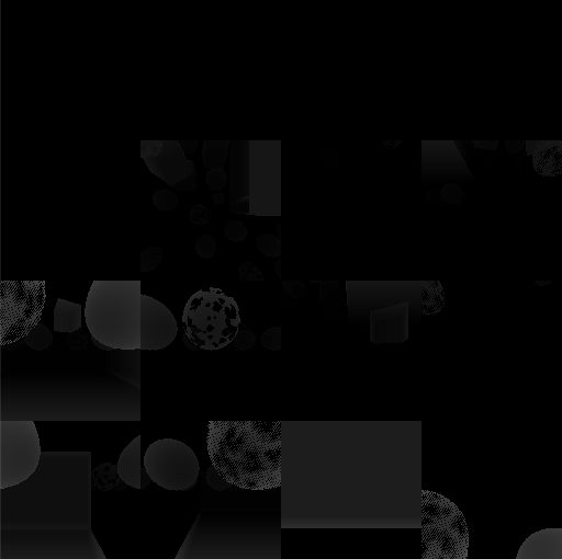
这如何改变渲染的阴影在比较阴影贴图时最为明显。
请注意,将 MeshRenderer 的 Cast Shadows 模式设置为 Two Sided 的对象不受影响,因为它们的任何面都不会被剔除。例如,我让所有带有 clip 或透明材质的球体投射双面阴影,所以它们看起来更实心。
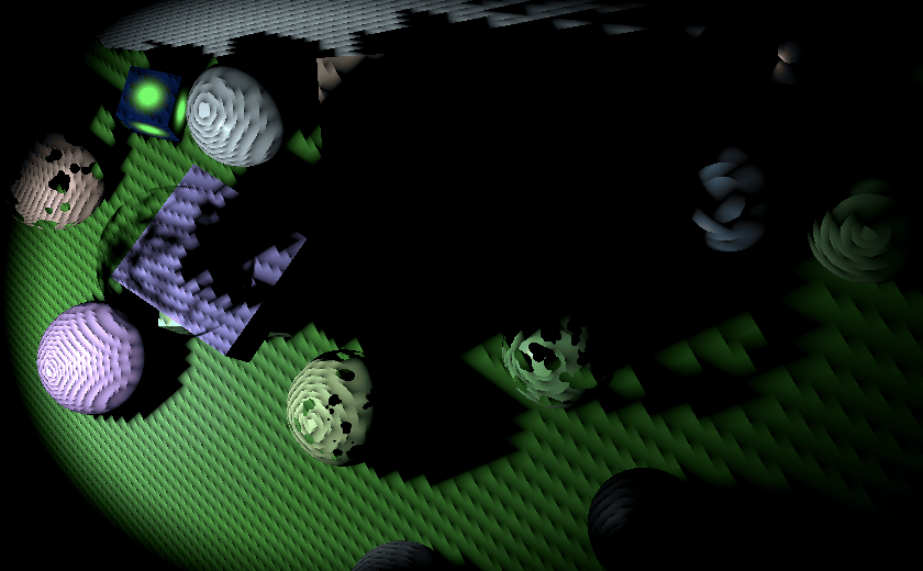
视野偏移
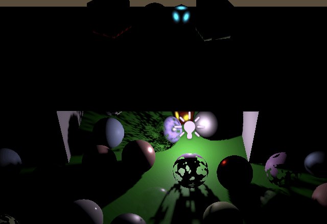
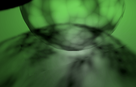
立方体贴图的面之间总是存在不连续性,因为纹理平面的方向突然改变 90°。常规立方体贴图采样可以在某种程度上隐藏这一点,因为它可以在面之间进行插值,但我们从每个片段的单个tiled采样。我们遇到了聚光阴影tiled边缘存在的相同问题,但现在它们没有被隐藏,因为没有聚光衰减。
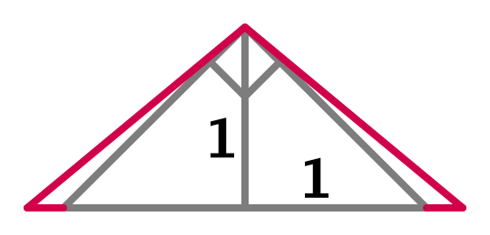
我们可以通过在渲染阴影时稍微增加视野(FOV)来减少这些伪影,这样我们就永远不会在tiled边缘之外采样。这就是 ComputePointShadowMatricesAndCullingPrimitives 的偏移参数的作用。我们通过使距离光源距离 1 处的tiled大小略大于 2 来实现这一点。具体来说,我们在每一侧添加法线偏移加上过滤器大小。然后对应的半 FOV 角度的正切值等于 1 加上偏移和过滤器大小。将其加倍,转换为度数,减去 90°,并在 RenderPointShadows 中将其用于 FOV 偏移。
1
2
3
4
5
6
7
8
9
10
float fovBias =
    Mathf.Atan(1f + bias + filterSize) * Mathf.Rad2Deg * 2f - 90f;
for (int i = 0; i < 6; i++) {
    cullingResults.ComputePointShadowMatricesAndCullingPrimitives(
        light.visibleLightIndex, (CubemapFace)i, fovBias,
        out Matrix4x4 viewMatrix, out Matrix4x4 projectionMatrix,
        out ShadowSplitData splitData
    );
    ...
}
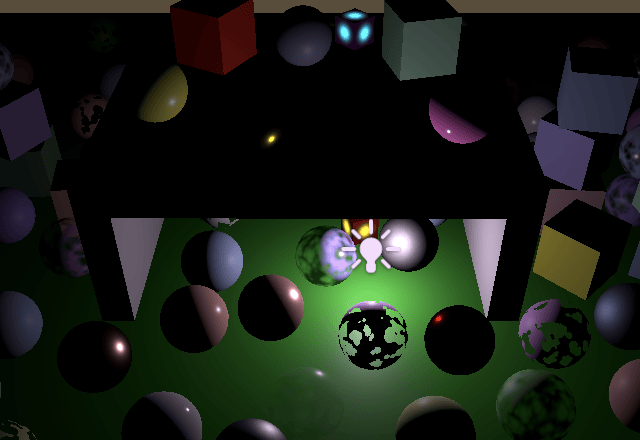
请注意,这种方法并不完美,因为通过增加tiled大小,纹素大小也会增加。因此,过滤器大小会增加,法线偏移也应该增加,这意味着我们必须再次增加 FOV。但是,差异通常足够小,我们可以忽略tiled大小的增加,除非结合使用大的法线偏移和过滤器与小的图集大小。
下一个教程是后期处理Post Processing